To preserve the feeling of old games, I wanted to give a “wireframe style” to my version of Lunar Lander. And while we could draw a sprite on the screen and scale/rotate it to have it our way, this does seem like an overkill solution for something as simple as drawing lines.
Drawing a bunch of lines is enough. But how to store the lander coordinates? X/Y pairs? Or polar coordinates? I chose the latter for it seemed the most elegant solution for such a rotational object. Let’s see this.
So, let’s start from there, and assume the only thing we have for now is a “draw line” function, which could be used that way:
void draw_line(x0, y0, x1, y1);This simply traces a segment from x0;y0 to x1;y1 on the screen. The implementation of such function is out of the scope of this post, but if you are interested, you can take a look at my primitives drawing functions.
This function is enough to draw anything wireframey, given we feed it with the correct data. So let’s define a set of points in 2D space:
#define LANDER_VERTICES_LEN 22
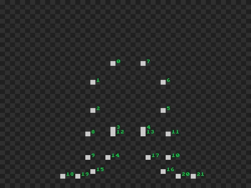
const float lander_coords[LANDER_VERTICES_LEN][2] = { {-3, -7}, {-7, -3}, {-7, 3}, {-3, 7}, {3, 7}, {7, 3}, {7, -3}, {3, -7}, {-8, 8}, {-8, 13}, {8, 13}, {8, 8}, {-3, 8}, {3, 8}, {-4, 13}, {-7, 16}, {7, 16}, {4, 13}, {-13, 17}, {-10, 17}, {10, 17}, {13, 17},};Alone, these are just pixel positions, without shaping anything yet. The pixel at index 0 is x = -3, y = -7 and so on. Displaying all pixels of this array on a canvas would render this:
Instead, let’s connect the dots! We now add a second array, that lists the lines that our lander is made of:
#define LANDER_EDGES_LEN 25
const size_t lander_edges[LANDER_EDGES_LEN][2] = {    // Head    {0, 1}, {1, 2}, {2, 3}, {3, 4}, {4, 5}, {5, 6}, {6, 7}, {7, 0},    //Base    {8, 9}, {9, 10}, {10, 11}, {11, 8},    // Neck    {3, 12}, {4, 13},    // Left Leg    {8, 18}, {18, 19}, {9, 19}, {9, 18},    // Right Leg    {11, 21}, {20, 21}, {10, 20}, {10, 21},    // Thrusters    {14, 15}, {15, 16}, {16, 17},};
Each pair in lander_edges describes a segment to draw, expressed in indices of lander_coords.
Thus, if we want for example to draw the 3rd line (index 2 in lander_edges), we do:
draw_line( lander_coords[lander_edges[2][0]][0], // Line 2, Coord 0, Axis 0 (X) lander_coords[lander_edges[2][0]][1], // Line 2, Coord 0, Axis 1 (Y) lander_coords[lander_edges[2][1]][0], // Line 2, Coord 1, Axis 0 (X) lander_coords[lander_edges[2][1]][1] // Line 2, Coord 1, Axis 1 (Y));Ok.
Combining this all in a loop through lander_edges is quite simple.
In the following code, I also shift all the coordinates by x and y, in order to center the drawing on the canvas:
int x = CANVAS_W / 2;int y = CANVAS_H / 2;
for (size_t e = 0; e < LANDER_EDGES_LEN; ++e) { const float x0 = lander_coords[lander_edges[e][0]][0]; const float y0 = lander_coords[lander_edges[e][0]][1]; const float x1 = lander_coords[lander_edges[e][1]][0]; const float y1 = lander_coords[lander_edges[e][1]][1];
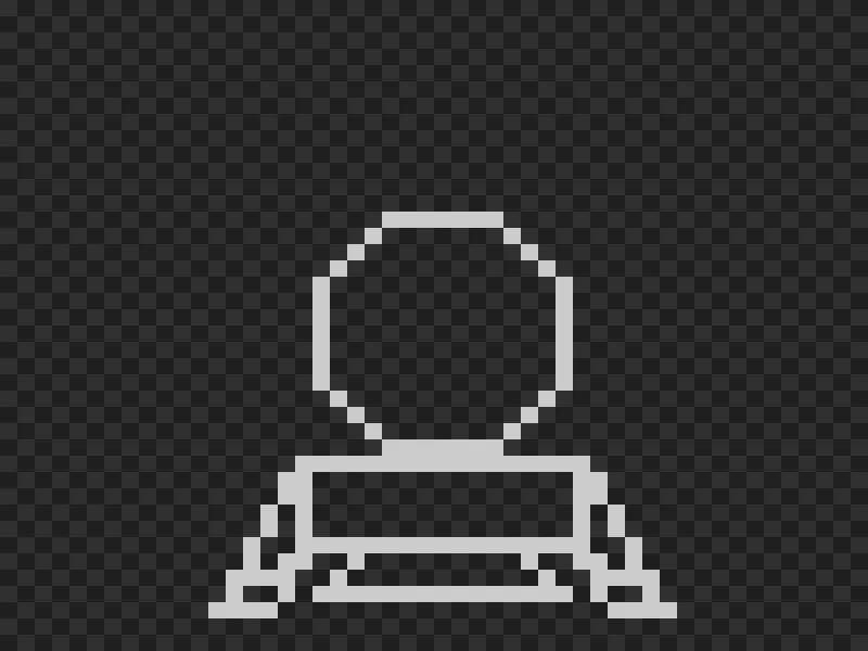
draw_line(x + x0, y + y0, x + x1, y + y1);}And here’s our lander, displayed on a 50x40 pixel grid:
Now, this is good, but rather inconvenient. Most of the time, the ship is rotating from the player’s inputs. The displacement of the ship entirely depends on its angle rather than being aligned to X or Y. It feels simpler to use polar coordinates instead.
While cartesian coordinates are used to express a position using a vector along each axis (X and Y), polar coordinates store two other pieces of information: how far the position is from the origin (the radius) and the angle the x/y vector makes from the X (or Y) axis.

So, first, let’s go back to the initial coordinates. But now, I’m also providing a new array of two floats. Each element of this new array is a [ρ, θ] pair, where ρ is the distance from origin, and θ is the angle between the X/Y vector, and the X axis.
We can quickly compute from cartesian to polar coordinates with and .
const int lander_xy_coords[][2] = {    // ... unchanged};
float lander_coords[LANDER_VERTICES_LEN][2]; // Now polar coordinates
for(size_t c = 0 ; c < LANDER_VERTICES_LEN ; ++c) {    const float x = lander_xy_coords[c][0];    const float y = lander_xy_coords[c][1];
    lander_coords[c][0] = sqrt(x * x + y * y);    lander_coords[c][1] = atan2f(y, x);}
The drawing part can now be updated to read the polar coordinates and convert them back to cartesian before calling draw_line.
Converting back to Cartesian gives and :
int x = CANVAS_W / 2;int y = CANVAS_H / 2;
float lander_angle = 0.f;float lander_size = 1.f;
for (size_t e = 0; e < LANDER_EDGES_LEN; ++e) {    const float r0 = lander_coords[lander_edges[e][0]][0] * lander_size;    const float a0 = lander_coords[lander_edges[e][0]][1] + lander_angle;    const float r1 = lander_coords[lander_edges[e][1]][0] * lander_size;    const float a1 = lander_coords[lander_edges[e][1]][1] + lander_angle;
    const float x0 = cosf(a0) * r0;    const float y0 = sinf(a0) * r0;    const float x1 = cosf(a1) * r1;    const float y1 = sinf(a1) * r1;
    draw_line(x + x0, y + y0, x + x1, y + y1);}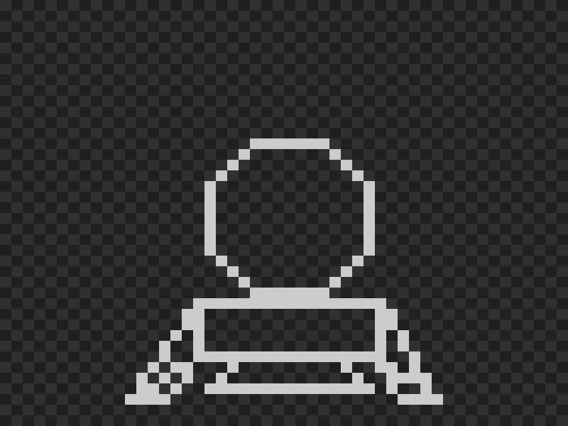
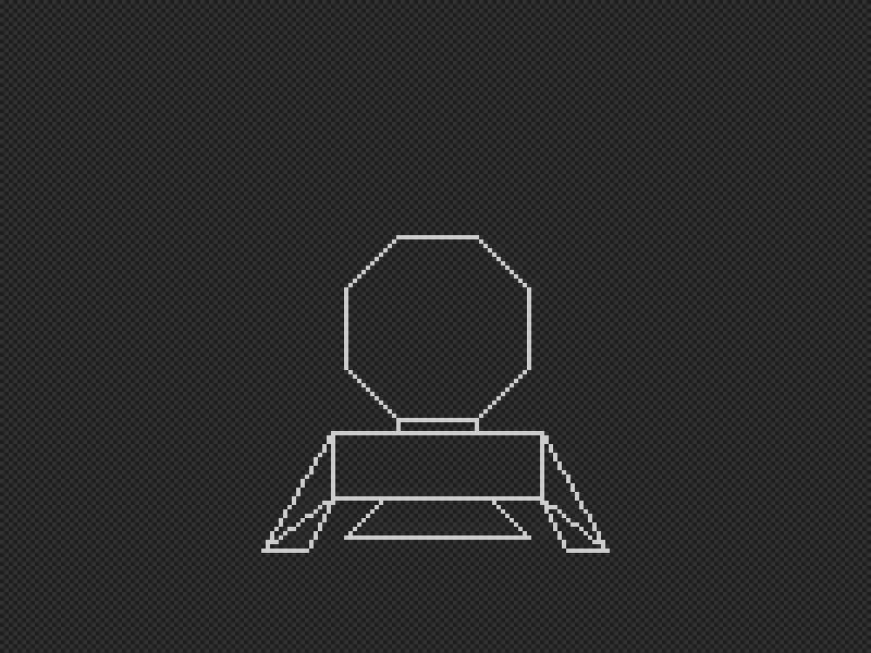
Ok, the display is a bit weird. The legs seem different compared to the previous draw. This is due to how low the resolution is and rounding/truncating floats. If we increase the game resolution, let’s say 200/150, we get a better result:
We may wonder why bother converting back and forth between polar and X/Y coordinates.
But now, manipulating the ship is really easy.
In the above snippet, I provide lander_angle and lander_size.
The former modifies the angle for all coordinates, and the latter changes the radius.
Now, after a small edit on the initial coordinates to lower the center of the ship, and add some green color, we have our ship.
We can play with lander_angle and lander_size to rotate and scale the lander:
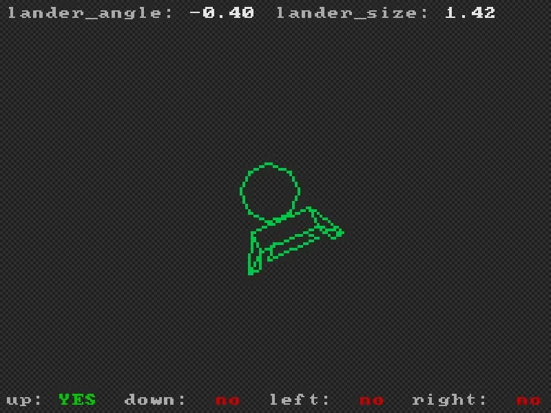
Polar coordinates make rotation dead simple: just add to the angle. Scaling? Multiply the radius. Sure, you convert back to X/Y for drawing, but that’s a small price for keeping the ship logic clean.
The concept extends to 3D with spherical coordinates—adding a second angle for elevation. Games like Elite (1984) used this for navigating 3D space, rotating around stars and planets with minimal math.
Not everything needs polar coordinates—your UI can stay in X/Y—but for objects that spin or scale from their center, it’s the natural fit.